Activity:
- Hardware design/casing for Ultrasonic Sensor module.
- Assembling and combining the Ultrasonic Sensor module (with casing) with the external body hardware.
- Proceed on designing the hardware for the system project.
- Analyzing the performance of the system hardware.
- The casing for the Ultrasonic Transmitter and Receiver was design using PVC pipes and perspex to protect the Sensor Module while giving it a proper body.
 |
| Receiver Sensor with its Casing |
Result & Analysis:
- The design for the system external hardware/body is normally just to shows the operation for the proposed system project as the design was constructed to look a little bit like a trolley.
- The performance of the Ultrasonic Sensor Module was tested after combining it with external hardware.
- Five Ultrasonic Receiver sensor was positioned on the top of the hardware with different angle position.
- Front-Left Receiver Sensor..................135°
- Front-Right Receiver Sensor..................45°
- Left Receiver Sensor............................180°
- Right Receiver Sensor..........................270°
- Back Receiver Sensor......................360°/0°
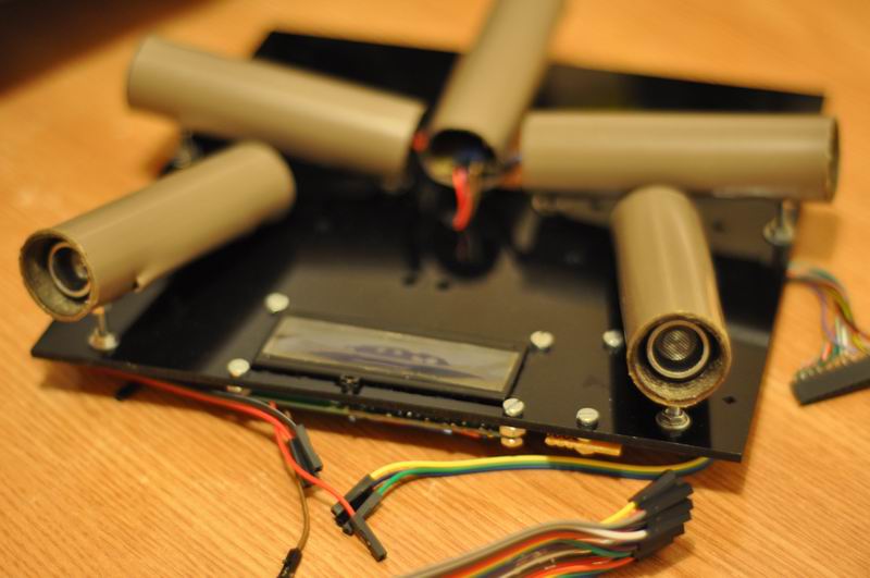 |
| Position of Ultrasonic Receiver Sensor |
 |
| System Design for the Project |
The constructing and designing the external hardware must be completed first before I can proceed into designing the coding as I need to analyze the position and the angle of the Receiver sensor. I've encountered a few problems during the designing progress;
- The L298N Motor Driver was unable to operate four DC Motor.
- The current supply is insufficient for drawing the DC Motor as all four DC Motor shows different speed.
- The performance for the Ultrasonic Transmitter was lesser as it is unable to generate the required signal power.
No comments:
Post a Comment